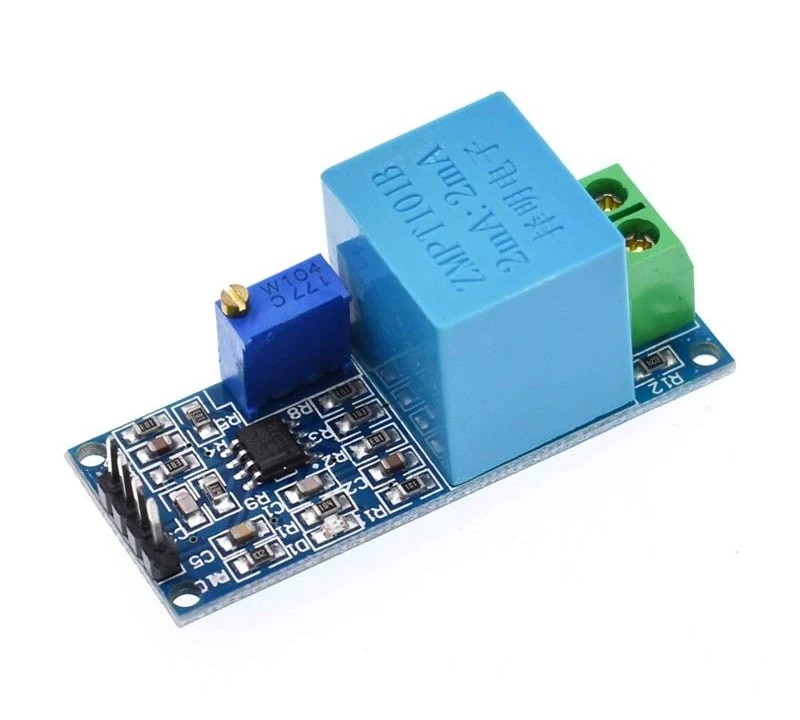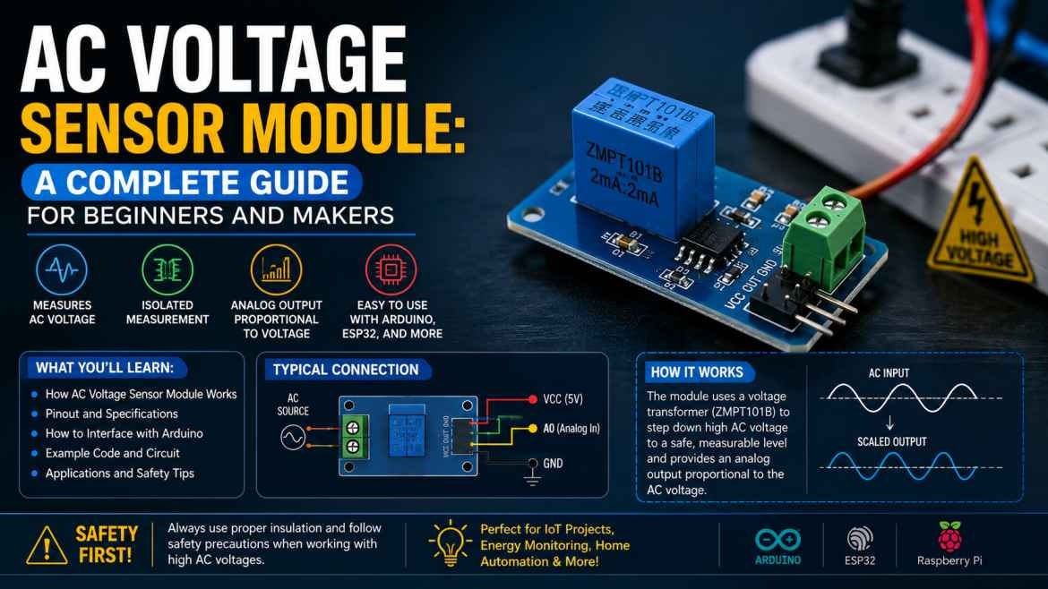
If you're building a project that needs to monitor mains power — like a smart energy meter, a home automation system, or a safety cutoff circuit — you'll eventually run into a problem: microcontrollers like Arduino and ESP32 can't safely read AC voltage directly. That's where the AC Voltage Sensor Module comes in.
In this guide, we'll explain what an AC voltage sensor module is, how it works, why it's essential for AC-based projects, and how to get started using one safely with Arduino or ESP32.
What Is an AC Voltage Sensor Module?
An AC voltage sensor module is a small electronic module designed to measure AC (alternating current) voltage — typically from mains power lines — and convert it into a safe, low-voltage analog signal that a microcontroller can read.
Since Arduino and ESP32 boards operate on 3.3V–5V DC logic, they cannot be connected directly to 220V/110V mains voltage without risking permanent damage or serious safety hazards. The AC voltage sensor module acts as a safe bridge: it steps down and isolates the high AC voltage, then outputs a proportional, low-voltage signal that your microcontroller can measure and interpret.
Most common modules, like the ZMPT101B-based sensor, are widely used for exactly this purpose in DIY and professional energy-monitoring projects.
Why Use an AC Voltage Sensor Module?
- Safety — it electrically isolates your microcontroller from dangerous mains voltage, protecting both your board and you.
- Accurate voltage monitoring — enables real-time tracking of AC voltage levels for energy monitoring or fault detection.
- Compact and beginner-friendly — most modules are small, breadboard-compatible, and easy to wire into existing projects.
- Wide compatibility — works with Arduino, ESP32, ESP8266, and other common microcontroller platforms.
- Enables smart applications — critical for building energy meters, voltage protection systems, and IoT-based power monitoring tools.
How Does an AC Voltage Sensor Module Work?
At a basic level, most AC voltage sensor modules work using a precision transformer that steps down the high AC input voltage to a much smaller, safe AC signal. This signal is then conditioned — often through an op-amp circuit — into an analog output centered around a reference voltage (commonly around 1.65V or 2.5V, depending on the module).
Your microcontroller reads this analog output using its ADC (analog-to-digital converter) pin. From there, code running on the board reconstructs the waveform and calculates the RMS (root mean square) voltage — giving you an accurate real-time reading of the actual mains voltage.
Because the sensing is done through a transformer, most of these modules also provide galvanic isolation, meaning there's no direct electrical connection between the mains side and your microcontroller — an important safety feature.
Common Applications of AC Voltage Sensor Modules
- Smart energy meters — measuring household or industrial power consumption in real time
- Home automation systems — monitoring voltage to detect power fluctuations or outages
- Voltage protection circuits — automatically cutting off appliances during dangerous over-voltage or under-voltage conditions
- IoT-based power monitoring — sending live voltage data to the cloud or a mobile app using ESP32's built-in Wi-Fi
- Solar and inverter systems — tracking input/output voltage for performance monitoring
- Industrial equipment monitoring — detecting abnormal voltage conditions that could indicate equipment issues
Components You'll Need for an AC Voltage Sensing Project
- An AC voltage sensor module (such as a ZMPT101B-based module)
- A microcontroller — Arduino Uno or ESP32, depending on whether you need Wi-Fi connectivity
- Jumper wires and a breadboard for prototyping
- A calibration reference — a multimeter to verify and calibrate your readings against known voltage values
- Optional: a display module (like an OLED or LCD) to show live voltage readings
- Optional: an ESP32 if you want to send voltage data to the cloud or a mobile app for remote monitoring
How to Get Started (Safely)
Working with AC mains voltage carries real risk, so a few safety notes come first:
- Never work on live AC wiring unless you're confident and experienced — when in doubt, consult a qualified electrician.
- Always double-check module wiring before connecting to mains power.
- Use modules with proper isolation, and avoid touching any part of the circuit while it's connected to AC power.
With that in mind, a typical setup looks like this:
- Connect the sensor module's low-voltage side to your microcontroller's analog input pin and power pins (following the specific module's datasheet).
- Connect the high-voltage side of the module to the AC source you want to measure — carefully, and with the power off during wiring.
- Upload sample code to read the analog output and calculate RMS voltage (most modules have example Arduino/ESP32 code available from the manufacturer or community).
- Calibrate your readings against a multimeter to fine-tune accuracy, since raw ADC readings usually need a calibration factor.
- Extend the project — log data over time, send it to the cloud via ESP32, or trigger alerts when voltage crosses a safe threshold.
Final Thoughts
AC voltage sensor modules are a small but essential component for anyone building energy monitoring, home automation, or power protection projects. They solve a real problem — safely bridging the gap between dangerous mains voltage and the low-voltage world of microcontrollers — while staying affordable and beginner-accessible.
Whether you're building a DIY energy meter, adding voltage protection to your home automation setup, or creating an IoT-based power monitoring system, an AC voltage sensor module is often the missing piece that makes safe, accurate mains voltage sensing possible.
Related products
Components that pair well with this guide.